


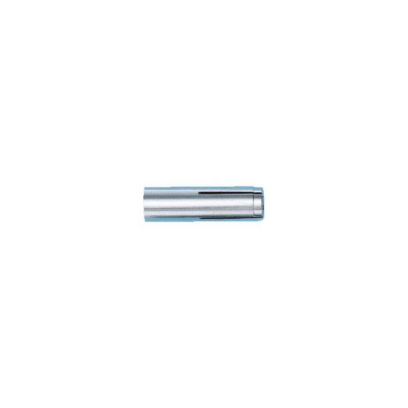


Drop-in anchor W-ED/A4
Drive-in dowel W-ED/A4, stainless steel A4
ANC-(W-ED/A4)-A4-M10


Register now and access more than 2,000 products
- ETA-02/0044 for individual fixing point, option 7, uncracked concrete
- ETA-05/0120 for anchors in a redundant non-structural system in non-load-bearing systems, uncracked and cracked concrete, M6-M16
- Fire resistance: F30, F60, F90 and F120; exposure to fire according to DIN 4102-2:1977-09 (uniform temperature curve)
- Fire resistance: R30, R60, R90 and R120; TR020 (included in ETA-05/0120)
Datasheets(X)
CAD data (available after login)

Anchor diameter | 10 mm |
Anchor length (L H) | 40 mm |
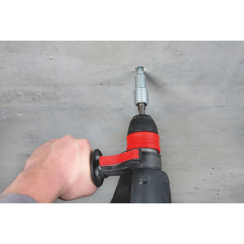
Min./max. required screw-in depth | 11-15 mm |
Material | Stainless steel A4 |
Nominal drill-bit diameter (d 0) | 12 mm |
Drill hole depth (h 0) | 40 mm |
Effective anchoring depth (h ef) | 40 mm |
Torque during anchoring (T inst) | 15 Nm |
Through-hole in the component to be connected (d f) | 12 mm |
Approval | ETA-02/0044, ETA-05/0120 |
| Performance data | |||||||||
| Anchor diameter [mm] | M6 | M8 | M10 | M12 | M16 | M20 | |||
| Admissible centric tension load1) on an individual anchor without the influence of the edge distance | Tensile zone (cracked concrete C20/252), s ≥ 3 hef, c ≥ 1.5 hef) | Nadm [kN] = C20/252) | 3,3 | 3,3 | 3,6 | 6,1 | 8,5 | 12,6 | 17,2 |
| Admissible shear load1) on an individual anchor without the influence of the edge distance | Compressive zone (uncracked concrete C20/252), c ≥ 10 hef) | Vadm [kN] = C20/252) | 3,2 | 4,6 | 6,0 | 11,9 | 19,2 | 30,7 | |
| Anchors in a redundant non-structural system in non-load-bearing systems in concrete3) | Fadm [kN] ≥ C20/25 | 1,2 | 1,7 | 2,0 | 2,0 | 2,4 | - | - | |
| Admissible bending moment | Madm (A4-70) [Nm] | 5,0 | 11,9 | 23,8 | 42,1 | 106,7 | 207,9 | ||
| Madm (A4-80) [Nm] | 6,4 | 16,1 | 32,2 | 56,4 | 142,9 | 278,7 | |||
| Admissible load when exposed to fire3) (Technical Report TR 020) For spacing and edge distances, see European Technical Approval ETA-05/0121 | R30; Fadm [kN] | 0,8 | 0,9 | 1,5 | 1,5 | - | - | ||
| R60; Fadm [kN] | 0,8 | 0,9 | 1,5 | 1,5 | - | - | |||
| R90; Fadm [kN] | 0,4 | 0,9 | 1,5 | 1,5 | - | - | |||
| Installation parameters | ||||||||
| M6 | M8x30 | M8x40 | M10 | M12 | M16 | M20 | ||
| Minimum spacing | smin [mm] | 50 | 60 | 80 | 100 | 120 | 150 | 160 |
| Minimum edge distance | cmin [mm] | 80 | 95 | 95 | 135 | 165 | 200 | 260 |
| Minimum member thickness | hmin [mm] | 100 | 100 | 100 | 130 | 140 | 160 | 250 |
| Effective anchorage depth | hef [mm] | 30 | 30 | 40 | 40 | 50 | 65 | 80 |
| Nominal drill diameter | d0 [mm] | 8 | 10 | 12 | 15 | 20 | 25 | |
| Diameter of cutting edges | dcut ≤ [mm] | 8,45 | 10,45 | 12,45 | 15,5 | 20,55 | 25,55 | |
| Drill hole depth | h0 = [mm] | 30 | 30 | 40 | 40 | 50 | 65 | 80 |
| Through hole in the component being connected | df ≤ [mm] | 7 | 9 | 12 | 14 | 18 | 22 | |
| Thread depth (max. length of thread engagement) | Lth [mm] | 13 | 13 | 20 | 15 | 18 | 23 | 34 |
| Installation parameters in concrete | |||||||
| Anchor size [mm] | M10x30 | M10x40 | M12x25 | M12x50 | M16x65 | M20x80 | |
| Standard component thickness | hmin,2 [mm] | 120 | 120 | 100 | 130 | 160 | 200 |
| Characteristic spacing of uncracked concrete/anchors in a redundant non-structural system | scr,N/scr | 3)/230 | 120/170 | -/- | 150/170 | 195/400 | 240/- |
| Characteristic edge distance of uncracked concrete/anchors in a redundant non-structural system | ccr,N/ccr | 3)/115 | 3)/3) | -/3) | 3)/3) | 3)/200 | 3)/- |
| Minimum spacing | smin [mm] | 100 | 100 | 100 | 120 | 150 | 160 |
| Minimum edge distance | cmin [mm] | 115 | 135 | 110 | 165 | 200 | 260 |
| Minimum member thickness | hmin,1 [mm] | - | - | 80 | - | - | - |
| Minimum spacing | smin [mm] | - | - | 100 | - | - | - |
| Minimum edge distance | cmin [mm] | - | - | 130 | - | - | - |
| Installation parameters in concrete | ||||||||
| Anchor size [mm] | M5x251) | M6x25 | M6x30 | M8x25 | M8x30 | M8x40 | M10x25 | |
| Standard component thickness | hmin,2 [mm] | 100 | 100 | 100 | 100 | 100 | 100 | 100 |
| Characteristic spacing of uncracked concrete/anchors in a redundant non-structural system | scr,N/scr | 75/- | -/75 | 90/130 | -/75 | 90/80 | 120/210 | -/75 |
| Characteristic edge distance of uncracked concrete/anchors in a redundant non-structural system | ccr,N/ccr | 3)/- | -/3) | 3)/3) | -/3) | 3)/3) | 3)/105 | -/3) |
| Minimum spacing | smin [mm] | 60 | 30 | 55 | 50 | 60 | 80 | 60 |
| Minimum edge distance | cmin [mm] | 95 | 60 | 95 | 100 | 95 | 95 | 100 |
| Minimum member thickness | hmin,1 [mm] | - | 80 | - | 80 | - | - | 80 |
| Minimum spacing | smin [mm] | - | 30 | - | 70 | - | - | 70 |
| Minimum edge distance | cmin [mm] | - | 60 | - | 100 | - | - | 100 |
Last viewed

VDE screwdriver, hexagon socket for working on live parts up to 1,000 V (AC) and up to 1,500 V (DC)

Insulated cable connector assortment

Rust remover Rost-Off

Water pump pliers DIN ISO 8976

1/2 inch POWERDRIV® socket wrench insert metric, bi-hex, long

Compressed-air filling station Refillo® combi

MFD-S multi-purpose drill bit with straight shank

Cable tie KBL 1 made of polyamide with plastic tongue

2-CUTTER SDS-PLUS HAMMER DRILL BITS Red Stripe

PH screwdriver with hexagon shank