


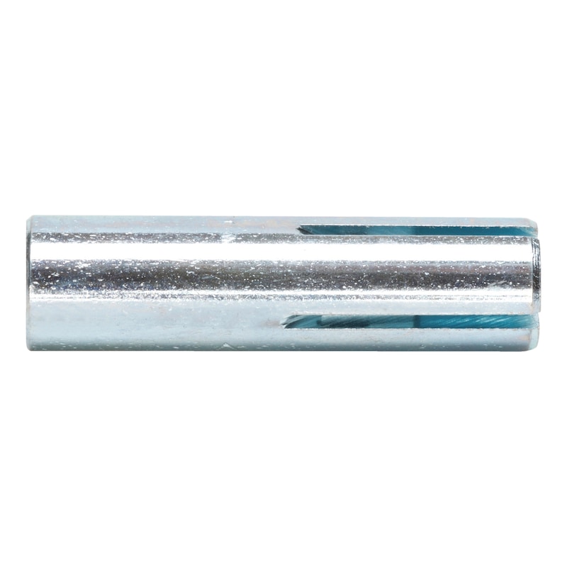


Drop-in anchor W-ED/S
Wedge anchor W-ED/S steel zinc plated
ANC-(W-ED/S)-(A2K)-M6


Register now and access more than 2,000 products
- Small drill hole depth
- High load-bearing capacities
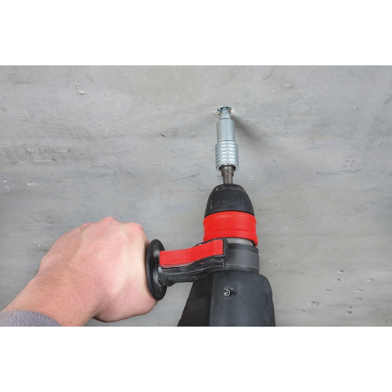
- Visual setting check and hand protection when installing with the marking/expander tool
- Mechanical setting tool makes installation quicker and easier
- Immediate load-bearing capacity – no waiting
- Attached part can easily be removed at any time
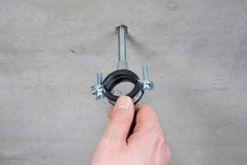
- The attached part can be anchored with a fastening screw or a threaded rod
- No installation torque required
- The stop bit used with the attachable expander tool makes it quicker and easier to install. The matching drill holes make the installation even more secure.
- ETA-02/0044 for individual fixing point, option 7, uncracked concrete
- ETA-05/0120 for anchors in a redundant non-structural system, uncracked and cracked concrete, M6-M16
- Fire resistance: F30, F60, F90 and F120; exposure to fire according to DIN 4102-2:1977-09 (UTTC - uniform temperature time curve)
- Fire resistance: R30, R60, R90 and R120; TR020 (included in ETA-05/0120)
Drive-in anchor W-ED/A4 see [13.2]
Drive-in anchor W-ED, M12 (for core drills), and W-ED, DW15, see [13.3]


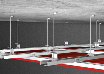 Suspended ceilings
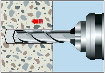
Drill the hole
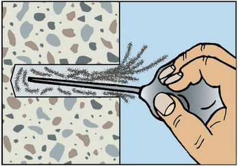
Clean the drill hole
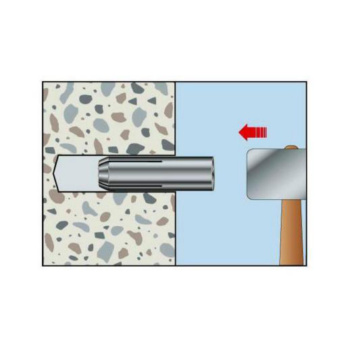
Knock in anchor until flush
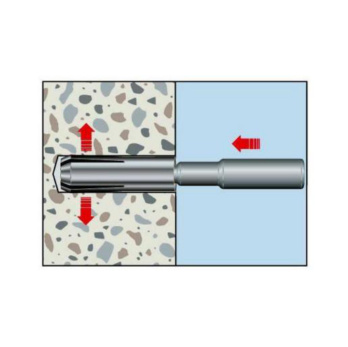
Anchor with expander tool
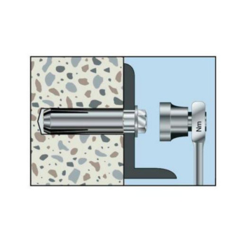
Fit component, apply torque
- ETA-02/0044 for individual fixing point, option 7, uncracked concrete
- ETA-05/0120 for anchors in a redundant non-structural system, uncracked and cracked concrete, M6-M16
- Fire resistance: F30, F60, F90 and F120; exposure to fire according to DIN 4102-2:1977-09 (UTTC - uniform temperature time curve)
- Fire resistance: R30, R60, R90 and R120; TR020 (included in ETA-05/0120)
Datasheets(X)
CAD data (available after login)

Individual fixing point: Normal weight concrete C20/25 to C50/60 (uncracked concrete)
Anchors in a redundant non-structural system: Anchorage of non-load-bearing systems (M6-M16, cracked and uncracked concrete)
E.g. threaded rods, metal structures, metal profiles, lattices, cable conduits, pipes, mounting rails etc.
For use in concrete < C20/25 and pressure-resistant natural stone (without approval)
May only be used in dry indoor conditions
Anchor diameter | 6 mm |
Anchor length (L H) | 30 mm |
Min./max. required screw-in depth | 7-13 mm |
Material | Steel |
Surface | Zinc plated |
Nominal drill-bit diameter (d 0) | 8 mm |
Drill hole depth (h 0) | 30 mm |
Effective anchoring depth (h ef) | 30 mm |
Torque during anchoring (T inst) | 4 Nm |
Through-hole in the component to be connected (d f) | 7 mm |
Approval | ETA-02/0044, ETA-05/0120 |
| Performance data in cracked and uncracked concrete - anchors in a redundant non-structural system (screw 4.6-8.8) | |||||||
| Anchor size [mm] | M10x25 | M10x30 | M10x40 | M12x25 | M12x50 | M16x65 | |
| Anchors in a redundant non-structural system in concrete10) | Fadm [kN] = C12/15 - C16/204) | 1.79) | - | - | 1.79) | - | - |
| Fadm [kN] = C20/25 - C50/604) | 2.19) | 2.09) | 2.09) | 2.19) | 2.49) | 6.39) | |
| Admissible bending moment7) | Madm [Nm] | 15,8 | 27,8 | 71,0 | |||
| Admissible load when exposed to fire10) | R30 [kN] | 0,6 | 0,9 | 1,5 | 0,6 | 1,5 | 4 |
| R60 [kN] | 0,6 | 0,9 | 1,5 | 0,6 | 1,5 | 4 | |
| R90 [kN] | 0,6 | 0,9 | 1,5 | 0,6 | 1,5 | 3,7 | |
| R120 [kN] | 0,5 | 0,7 | 1,0 | 0,5 | 1,2 | 2,4 | |
| Performance data in cracked and uncracked concrete - anchors in a redundant non-structural system (screw 4.6-8.8) | ||||||
| Anchor size [mm] | M6x25 | M6x30 | M8x25 | M8x30 | M8x40 | |
| Anchors in a redundant non-structural system in concrete10) | Fadm [kN] = C12/15 - C16/204) | 1,2 | - | 1,2 | - | - |
| Fadm [kN] = C20/25 - C50/604) | 1.79) | 1,2 | 1.99) | 1.79) | 2.09) | |
| Admissible bending moment7) | Madm [Nm] | 3,3 | 8,1 | |||
| Admissible load when exposed to fire10) | R30 [kN] | 0,4 | 0,8 | 0,6 | 0,9 | 1,5 |
| R60 [kN] | 0,4 | 0,8 | 0,6 | 0,9 | 1,5 | |
| R90 [kN] | 0,3 | 0,4 | 0,6 | 0,9 | 0,9 | |
| R120 [kN] | 0,3 | 0,3 | 0,5 | 0,5 | 0,5 | |
| Performance data in uncracked concrete - individual fixing point (screw 4.6-8.8) | ||||||
| Anchor size [mm] | M10x40 | M12x50 | M16x65 | M20x80 | ||
| Admissible centric tension load3) on an individual anchor without the influence of the edge distance | Compressive zone (uncracked concrete C20/254), s ≥ 3 hef, c ≥ cmin) | Nadm [kN] = C20/244) | 5,1 | 7,1 | 10,5 | 14,3 |
| Admissible shear load3) on an individual anchor without the influence of the edge distance | Compressive zone (uncracked concrete C20/254), s ≥ 3 hef, c ≥ cmin) | Vadm [kN] = C20/244)5) | 4,1 | 9,0 | 16,8 | 26,2 |
| Admissible bending moment7) | Madm [Nm] | 27,8 | 71,0 | 138,6 | ||
| Fire resistance8) according to UTTC (uniform temperature time curve) | F30 [kN] | 4,7 | 6,9 | 12,5 | 18,0 | |
| F60 [kN] | 2,4 | 3,5 | 5,6 | 8,5 | ||
| F90 [kN] | 1,3 | 1,8 | 3,5 | 5,5 | ||
| F120 [kN] | 1,0 | 1,4 | 2,5 | 4,4 | ||
| Performance data in uncracked concrete - individual fixing point (screw 4.6-8.8) | |||||||
| Anchor size [mm] | M5x251)6) | M6x306) | M8x306) | M8x40 | M10x306) | ||
| Admissible centric tension load3) on an individual anchor without the influence of the edge distance | Compressive zone (uncracked concrete C20/254), s ≥ 3 hef, c ≥ cmin) | Nadm [kN] = C20/244) | Frec 1.4 | 3,3 | 3,3 | 3,6 | 3,3 |
| Admissible shear load3) on an individual anchor without the influence of the edge distance | Compressive zone (uncracked concrete C20/254), s ≥ 3 hef, c ≥ cmin) | Vadm [kN] = C20/244)5) | Frec 1.5 | 2,1 | 3,9 | 3,9 | 4,0 |
| Admissible bending moment7) | Madm [Nm] | - | 3,3 | 8,1 | 15,8 | ||
| Fire resistance8) according to UTTC (uniform temperature time curve) | F30 [kN] | - | 1,7 | 1,7 | 3,0 | - | |
| F60 [kN] | - | 0,7 | 0,7 | 1,5 | - | ||
| F90 [kN] | - | 0,4 | 0,4 | 0,8 | - | ||
| Performance data (screw 5.6-8.8) | |||||||
| Anchor diameter [mm] | M58) | M68) | M8 x 308) | M8 x 40 | M10 x 308) | ||
| Admissible centric tension load1) on an individual anchor without the influence of the edge distance | Compressive zone (uncracked concrete C20/252), s ≥ 3 hef, c ≥ cmin) | Nadm [kN] = C20/252) | Frec 1.4 | 3,3 | 3,3 | 3,6 | 3,3 |
| Admissible shear load1) on an individual anchor without the influence of the edge distance | Compressive zone (uncracked concrete C20/252), c ≥ 10 hef) | Vadm [kN] = C20/25 2) 3) | Frec 1.5 | 2,1 | 3,9 | 3,9 | 4,0 |
| Anchors in a redundant non-structural system in concrete4) | Fadm [kN] ≥ C20/25 | 1,2 | 1.79) | 2.09) | 2.09) | ||
| Admissible bending moment 5) uncracked concrete/anchors in a redundant non-structural system | Madm [Nm] | - | 3.3/ 3.3 | 8.1/ 8.1 | 15.8/ 15.8 | ||
| Admissible load when exposed to fire 4) (Technical Report TR 020) For axis and edge distances, see European Technical Approval ETA-05/0120 | R30; Fadm [kN] | - | 0,8 | 0,9 | 1,5 | 0,9 | |
| R60; Fadm [kN] | - | 0,8 | 0,9 | 1,5 | 0,9 | ||
| R90; Fadm [kN] | - | 0,4 | 0,9 | 0,9 | 0,9 | ||
| R120; Fadm [kN] | - | 0,3 | 0,5 | 0,5 | 0,7 | ||
| Fire resistance rating6) according to UTTC (uniform temperature time curve) | F30 [kN] | - | 1,7 | 1,7 | 3,0 | - | |
| F60 [kN] | - | 0,7 | 0,7 | 1,5 | - | ||
| F90 [kN] | - | 0,4 | 0,4 | 0,8 | - | ||
| Installation parameters in concrete | ||||||||
| Anchor size [mm] | M10x25 | M10x30 | M10x40 | M12x25 | M12x50 | M16x65 | M20x80 | |
| Standard component thickness | hmin,2 [mm] | 100 | 120 | 120 | 100 | 130 | 160 | 200 |
| Characteristic axis distance of uncracked concrete/anchors in a redundant non-structural system | scr,N/scr | –/75 | 3)/230 | 120/170 | –/– | 150/170 | 195/400 | 240/– |
| Characteristic edge distance of uncracked concrete/anchors in a redundant non-structural system | ccr,N/ccr | –/3) | 3)/115 | 3)/3) | –/3) | 3)/3) | 3)/200 | 3)/– |
| Minimum axis distance | smin [mm] | 60 | 100 | 100 | 100 | 120 | 150 | 160 |
| Minimum edge distance | cmin [mm] | 100 | 115 | 135 | 110 | 165 | 200 | 260 |
| Minimum member thickness | hmin,1 [mm] | 80 | - | - | 80 | - | - | - |
| Minimum edge distance | cmin [mm] | 100 | - | - | 130 | - | - | - |
| Installation parameters in concrete | |||||||
| Anchor size [mm] | M5x251) | M6x25 | M6x30 | M8x25 | M8x30 | M8x40 | |
| Standard component thickness | hmin,2 [mm] | 100 | 100 | 100 | 100 | 100 | 100 |
| Characteristic axis distance of uncracked concrete/anchors in a redundant non-structural system | scr,N/scr | 75/– | –/75 | 90/130 | –/75 | 90/80 | 120/210 |
| Characteristic edge distance of uncracked concrete/anchors in a redundant non-structural system | ccr,N/ccr | 3)/– | –/3) | 3)/3) | –/3) | 3)/3) | 3)/105 |
| Minimum axis distance | smin [mm] | 60 | 30 | 55 | 50 | 60 | 80 |
| Minimum edge distance | cmin [mm] | 95 | 60 | 95 | 100 | 95 | 95 |
| Minimum member thickness | hmin,1 [mm] | - | 80 | - | 80 | - | - |
| Minimum axis distance | smin [mm] | - | 30 | - | 70 | - | - |
| Installation parameters | ||||||||||
| M57) | M6 | M8 x 30 | M8 x 40 | M10 x 30 | M10 x 40 | M12 | M16 | M20 | ||
| Minimum axis distance | smin [mm] | 60 | 55 | 60 | 80 | 100 | 100 | 120 | 150 | 160 |
| Minimum edge distance | cmin [mm] | 95 | 95 | 95 | 95 | 115 | 135 | 165 | 200 | 260 |
| Minimum member thickness | hmin [mm] | 100 | 100 | 100 | 100 | 120 | 120 | 130 | 160 | 200 |
| Effective anchorage depth | hef [mm] | 25 | 30 | 30 | 40 | 30 | 40 | 50 | 65 | 80 |
| Nominal drill ∅ | d0 [mm] | 8 | 8 | 10 | 10 | 12 | 12 | 15 | 20 | 25 |
| Drill cutting ∅ | dcut ≤ [mm] | 8,45 | 8,45 | 10,45 | 10,45 | 12,5 | 12,5 | 15,5 | 20,55 | 25,55 |
| Drill hole depth | h0 = [mm] | 25 | 30 | 30 | 40 | 30 | 40 | 50 | 65 | 80 |
| Through hole in the component being connected | df ≤ [mm] | 6 | 7 | 9 | 9 | 12 | 12 | 14 | 18 | 22 |
| Performance data (screw 5.6-8.8) | ||||||
| Anchor diameter [mm] | M10 x 40 | M12 | M16 | M20 | ||
| Admissible centric tension load1) on an individual anchor without the influence of the edge distance | Compressive zone (uncracked concrete C20/252), s ≥ 3 hef, c ≥ cmin) | Nadm [kN] = C20/252) | 5,1 | 7,1 | 10,5 | 14,3 |
| Admissible shear load1) on an individual anchor without the influence of the edge distance | Compressive zone (uncracked concrete C20/252), c ≥ 10 hef) | Vadm [kN] = C20/25 2) 3) | 4,1 | 9,0 | 16,8 | 26,2 |
| Anchors in a redundant non-structural system in concrete4) | Fadm [kN] ≥ C20/25 | 2.09) | 2.49) | 6.39) | - | |
| Admissible bending moment 5) uncracked concrete/anchors in a redundant non-structural system | Madm [Nm] | 27.8/ 27.8 | 71.0 71.0 | 138,6 | ||
| Admissible load when exposed to fire 4) (Technical Report TR 020) For axis and edge distances, see European Technical Approval ETA-05/0120 | R30; Fadm [kN] | 1,5 | 1,5 | 4,0 | - | |
| R60; Fadm [kN] | 1,5 | 1,5 | 4,0 | - | ||
| R90; Fadm [kN] | 1,5 | 1,5 | 3,7 | - | ||
| R120; Fadm [kN] | 1,0 | 1,2 | 2,4 | - | ||
Last viewed

Radiator Coolent Water Based

Hammer drill bit Plus Duo-S Vario

HSS 90° yellow-ring countersink DIN 335C

Pipe clamp, two-part, with rubber

Active Clean vehicle cleaner
Screwdriver with AW tip

Tyre pressure monitoring system, tool set For the professional installation of tyre pressure monitoring sensors

C 6.3 bit hexagon socket (1/4 inch) with patented POWERDRIV® drive

Suction cup For valve seat grinder

Tool case 16 pieces in system case 8.4.1.