


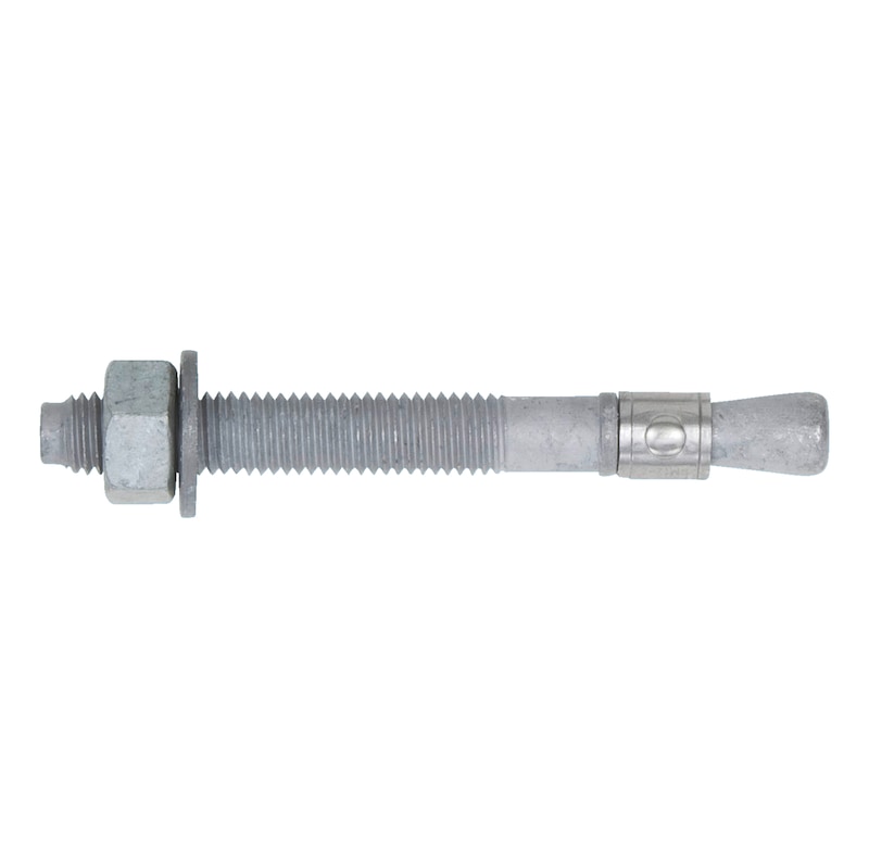


Fixanchor W-FA/F
Fixanchor W-FA steel hot dip galvanized
ANC-(W-FA/F)-(HDG)-20/26-M10X95


Register now and access more than 2,000 products
- Time-saving push-through installation
- Immediate load-bearing capacity — no waiting
- Torque-controlled expanding anchor made from hot dip galvanised steel
- Two anchorage depths — wide range of applications
ETA-02/0001 for individual fixing point, option 7, uncracked concrete
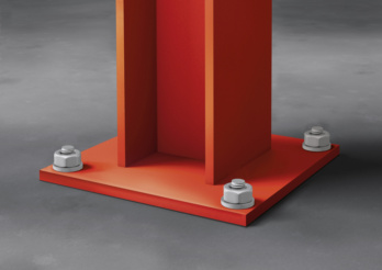 Heavy steel structures
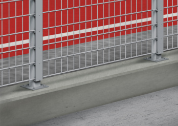 Fence systems
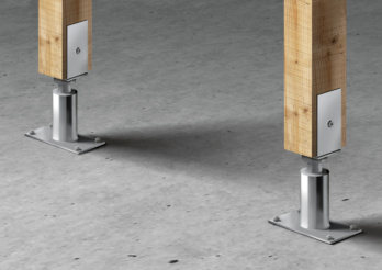 Post support bracket
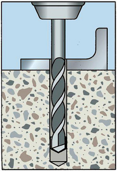
Create the drill hole
10
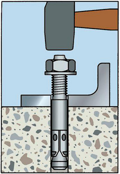
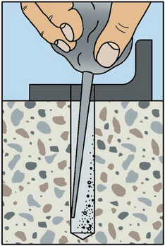
Knock in anchor with mason's mallet or machine setting tool

Set anchor in place
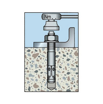
Apply torque
ETA-02/0001 for individual fixing point, option 7, uncracked concrete
Datasheets(X)

- Individual fixing point: Normal weight concrete C20/25 to C50/60 (uncracked concrete)
- Suitable for fastening metal structures, metal profiles, brackets, base plates, supports, cable conduits, pipes, wooden structures, beams, purlins etc.
- For use in concrete < C20/25 and pressure-resistant natural stone (without approval)
- The anchor may be used for anchorages with predominantly static loads (e.g. tare weight, fittings, stored materials) or quasi-static loads (e.g. façades, staircase railings)
- W-FA/F may only be used in dry indoor conditions
 | |
Metric anchor diameter | M10 |
Anchor length (l) | 95 mm |
Material | Steel |
Surface | Hot dip galvanized |
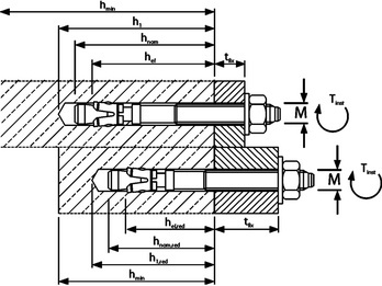
Attachment height (t fix) | 20 mm |
Attachment height (t fix 2) | 48 mm |
Drill hole depth (h 1) | 26 mm |
Drill hole depth (h 1.2) | 42 mm |
Effective anchoring depth (h ef) | 26 mm |
Effective anchoring depth (h ef 2) | 42 mm |
Width across flats | 10 mm |
Approval | ETA, ETA-02/0001 |
| Performance data | ||||||||||||||
| Anchor diameter [mm] | M6 | M8 | M10 | M12 | M16 | M20 | ||||||||
| Standard effective anchorage depth/reduced effective anchorage depth | hef/hef red [mm] | 40 | 30 | 44 | 35 | 48 | 42 | 65 | 50 | 82 | 64 | 100 | 78 | |
| Admissible centric tension load1) on an individual anchor without the influence of the edge distance | Compressive zone (uncracked concrete) C20/252), s ≥ 3 hef c ≥ 1.5 hef) | Nadm [kN] = C20/252) | 4,1 | 2,9 | 5,7 | 5,0 | 7,6 | 6,5 | 12,6 | 8,5 | 17,8 | 12,3 | 24 | 16,5 |
| Admissible shear load1) on an individual anchor without the influence of the edge distance | Compressive zone (uncracked concrete C20/252), c ≥ 10 hef) | Vadm [kN] = C20/252) | 2,9 | 2,9 | 6,3 | 5,0 | 8,0 | 6,5 | 14,3 | 8,5 | 23,6 | 23,6 | 37,1 | 33,1 |
| Admissible bending moment | Madm [Nm] | 5,1 | 5,1 | 13,1 | 13,1 | 25,7 | 25,7 | 44,6 | 44,6 | 99,9 | 99,9 | 195 | 195 | |
| Fire resistance rating (W-FA/S) | F30 [kN] | 0,9 | - | 1,4 | - | 2,2 | - | 3,2 | - | 6,0 | - | 10,0 | - | |
| F60 [kN] | 0,5 | - | 0,8 | - | 1,2 | - | 1,8 | - | 3,4 | - | 5,25 | - | ||
| Characteristic values | |||||||||||||
| Embedment depth | hnom/hnom,red [mm] | 49 | 39 | 56 | 47 | 62 | 56 | 82 | 67 | 102 | 84 | 121 | 99 |
| Nominal drill ∅ | d0 [mm] | 6 | 6 | 8 | 8 | 10 | 10 | 12 | 12 | 16 | 16 | 20 | 20 |
| Drill cutting ∅ | dcut ≤ [mm] | 6,4 | 6,4 | 8,45 | 8,45 | 10,45 | 10,45 | 12,5 | 12,5 | 16,5 | 16,5 | 20,55 | 20,55 |
| Drill hole depth | h1/h1,red ≥ [mm] | 55 | 45 | 65 | 55 | 70 | 65 | 90 | 75 | 110 | 95 | 130 | 110 |
| Through hole in the component being connected | df ≤ [mm] | 7 | 7 | 9 | 9 | 12 | 12 | 14 | 14 | 18 | 18 | 22 | 22 |
| Torque while installing anchor (W-FA/S, zinc-plated steel) | Tinst = [Nm] | 8 | 8 | 15 | 15 | 30 | 30 | 50 | 50 | 100 | 100 | 200 | 200 |
| Torque while installing anchor (W-FA/F, hot-dip galvanised steel) | Tinst = [Nm] | - | - | 15 | 15 | 30 | 30 | 40 | 40 | 90 | 90 | 120 | 120 |
| Individual fixing point | |||||||||||||
| Uncracked concrete, option 7 (ETA-02/0001 - zinc-plated steel and hot-dip galvanised steel) | |||||||||||||
| Standard effective anchorage depth/reduced effective anchorage depth | hef/hef,red [mm] | 40 | 30 | 44 | 35 | 48 | 42 | 65 | 50 | 82 | 64 | 100 | 78 |
| Axis distance | scr,N [mm] | 120 | 90 | 132 | 105 | 144 | 126 | 195 | 150 | 246 | 192 | 300 | 234 |
| Edge distance | ccr,N [mm] | 60 | 45 | 66 | 53 | 72 | 63 | 98 | 75 | 123 | 96 | 150 | 117 |
| Minimum axis distance | smin [mm] | 35 | 35 | 40 | 40 | 55 | 55 | 75 | 100 | 90 | 100 | 105 | 140 |
| Minimum edge distance | cmin [mm] | 40 | 40 | 45 | 45 | 65 | 65 | 90 | 100 | 105 | 100 | 125 | 140 |
| Minimum member thickness | hmin [mm] | 100 | 80 | 100 | 80 | 100 | 100 | 130 | 100 | 170 | 130 | 200 | 160 |
Last viewed

Joint bar socket wrench

Safety shear pin for MacPherson spring strut compressor

Multi-purpose carbide drill bit
Safety shoes S1P New Poseidon

Soft manual polishing pad

Chop and table saw KTS 140 Combi

1C cutter knife with clamping wheel

Circlip pliers, shape C For bore circlips

1-inch impact socket wrench insert hexagon, metric, short

Metric ratchet combination wrench Flexible ratchet head with POWERDRIV®